Broward A&C Medical Gas Installation Kit Operating Manual / Field Use Guide
(NFPA 99–Aligned)
This manual is prepared for medical gas installers working under NFPA 99 (2025 Edition as adopted by the Authority Having Jurisdiction – AHJ).
1. Purpose and Scope of this Manual
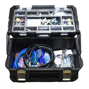
The Broward A&C Medical Gas Installation Kit is a professional, field-ready toolkit developed to support compliant installation, modification, repair, testing, and commissioning of medical gas and vacuum piping systems. These systems are critical life-safety utilities used in hospitals, ambulatory surgical centers, dental clinics, laboratories, and other healthcare environments governed by NFPA 99: Health Care Facilities Code.
This Operating Manual is written as a practical field use guide. It explains why each component exists, when it must be used, and how it supports code compliance. The intent is to help installers perform work that is safe, repeatable, verifiable, and defensible during inspection or third-party verification.
This manual is designed to be used:
- During new medical gas installations
- During renovations, expansions, or system tie-ins
- During repairs requiring brazing or system depressurization
- During pressure testing, purging, and commissioning
This document does not replace or override:
- NFPA 99 or any locally adopted amendments
- ASSE 6010 installer training or certification
- ASSE 6030 verification requirements
- Project drawings, specifications, or sequencing plans
- Manufacturer instructions for individual tools or instruments
- Authority Having Jurisdiction (AHJ) interpretations
Installers are responsible for ensuring all work complies with the specific edition of NFPA 99 adopted locally, as well as all applicable building, fire, and healthcare regulations.
2. Regulatory Framework and Code Responsibility
Medical gas systems are regulated because failure can result in serious injury or loss of life. These systems are different from conventional piping systems because medical gas piping must meet strict requirements for cleanliness, material compatibility, pressure integrity, labeling, and verification.
NFPA 99 establishes minimum safety standards covering:
- System materials and components
- Installation and brazing practices
- Purging and cleanliness controls
- Pressure testing and leak testing
- Verification, documentation, and acceptance
The Broward A&C Medical Gas Installation Kit is assembled specifically to support these requirements. The kit helps installers demonstrate compliance when used correctly. The kit contains elements with key NFPA 99 provisions related to:
- Continuous nitrogen purging during brazing
- Prevention of internal oxidation and particulate contamination
- Controlled pressure testing using inert gas
- Verification of oxygen purity
- Proper connection to outlets and DISS test points
Failure to follow these requirements may result in:
- Failed inspections
- Rejected verification reports
- Delays in occupancy or licensure
- Unsafe conditions for patients and staff
3. Installer Qualifications and Safety Obligations
3.1 Installer Qualifications
All personnel performing medical gas work must be qualified and competent. In most jurisdictions, this includes ASSE 6010 Medical Gas Installer certification, or equivalent credentials accepted by the AHJ.
Installers must be familiar with:
- NFPA 99 guidelines
- Brazing procedures and metallurgy
- Cleanliness and contamination control
- Pressure testing protocol
- System documentation practices
Unqualified personnel must not perform brazing, pressure testing, or system tie-ins.
3.2 Brazing Qualification
Brazing shall be performed using a qualified brazing procedure in accordance with:
- ASME Section IX
or
- AWS B2.2
Only filler metals approved for medical gas service shall be used. Silver-bearing filler metals are commonly required depending on project specifications.
3.3 General Safety Requirements
Wear appropriate PPE at all times, including safety glasses and gloves.
- Use fire-resistant clothing when brazing
- Maintain a fire watch as required by site policy
- Ensure adequate ventilation when purging with nitrogen
- Never use oxygen or medical air for purging or pressure testing
- Treat nitrogen as an asphyxiation hazard in confined spaces
3.4 Code Compliance
- Follow the edition of NFPA 99 adopted by the AHJ
- Follow all project drawings, specifications, and commissioning requirements
- Do not deviate from approved documents without written authorization
- Kit Components and Functional Overview
The Broward A&C Medical Gas Installation Kit contains tools selected specifically for medical gas work. Each component supports a defined compliance or safety function.
4.1 Major Components
| Component | Primary Use | Key Notes |
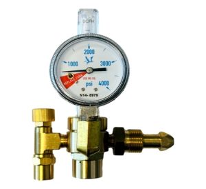
| Nitrogen pressure regulator (CGA 580, 0–400 psi)
|
Pressure testing and system pressurization | Connects to N₂ cylinder |
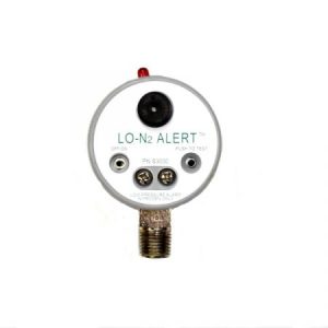
| Nitrogen purge regulator with flowmeter (0–60 SCFH) and low N₂ alarm gauge
|
Continuous purge during brazing | Controls purge flow into copper lines; Monitors cylinder depletion |
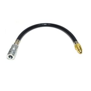
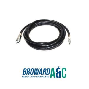
| Medical grade non-conductive N₂ purge hoses (15 ft & 1 ft, with quick connects)
|
Connecting regulators to system for purge and test connections | 250 psi max |
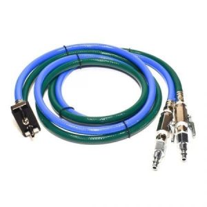
| Dual O₂/N₂O purge hose for Porter dental outlets
|
Purging dental piping via existing outlets | Has shutoff valves & quick-connects |
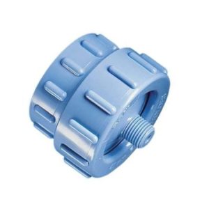
| In-line particulate filter holder + 45-micron filters
|
Keep purge gas clean | Used only for NFPA 99 particulate matter testing (not for installation or purging) |
| Tee purge adapter with 400 psi gauge, valves & quick connects
|
Purging and pressure monitoring | Used during purging and testing |
| Maxtec O₂ analyzer with adapters
|
Verifying oxygen levels & contamination | Used post-purge and pre-service acceptance |
| Ohmeda, Chemetron, Puritan-Bennett male quick connects (O₂, N₂O, AIR, VAC, WAGD)
|
Connecting to different outlet types | For multiple manufacturers |
| DISS hand-tight connectors (O₂, N₂O, AIR, VAC, WAGD, N₂)
|
DISS connections for systems | Diameter Index Safety System |
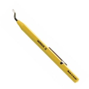
| Deburring tool & Scotch-Brite pads
|
Prep oxygen-clean copper | For ASTM B819 K/L oxygen-cleaned copper |
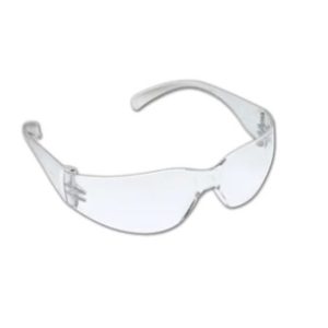
| Safety glasses
|
Personal protective equipment | PPE |
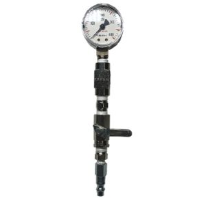
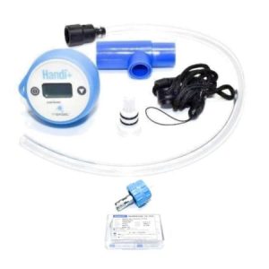
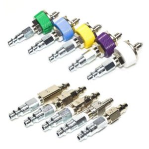
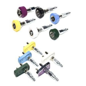
All components are intended for use with medical gas systems and should be kept clean and free from oil, grease, or other contaminants.
5. Copper Tubing Requirements and Preparation
5.1 Approved Materials
Medical gas piping must be constructed of ASTM B819 oxygen-cleaned copper tubing. Only tubing that is factory-cleaned and capped is permitted.
Type K or Type L copper shall be used as required by system pressure and project specifications. Tubing ends must remain capped until immediately before installation.
5.2 Cutting and Deburring
- Proper tube preparation is critical to cleanliness and joint integrity
- Cut the tubing square using a tubing cutter
- Remove all internal burrs using the deburring tool
- Clean tube ends with Scotch-Brite pads until bright and bare copper is visible
Failure to deburr or clean tubing can introduce particulate matter that compromises system performance.
5.3 Clean Handling Practices
- Do not touch the cleaned tube ends with bare hands
- Keep tubing capped when not actively being worked on
- Do not introduce oils, lubricants, tape residue, or other contaminants
- Do not allow tubing to contact floors or dirty surfaces
- Cap open piping immediately if work is interrupted
6. Nitrogen Regulator Setup and Hose Connections
6.1 Pressure Regulator Setup
The nitrogen pressure regulator is used for pressure testing and controlled system pressurization.
- Inspect the nitrogen cylinder and regulator for damage
- Briefly crack the cylinder valve to clear dust or debris
- Attach the pressure regulator to the CGA 580 cylinder valve
- Ensure the regulator adjusting screw is backed out (zero pressure)
- Connect the nitrogen hose to the regulator outlet
- Slowly open the cylinder valve
6.2 Purge Regulator Setup
The purge regulator provides low-flow nitrogen during brazing
- Mount the purge regulator securely to the nitrogen cylinder
- Connect the purge hose to the outlet
- Verify the flowmeter operates smoothly from 0–60 SCFH
- Ensure the low‑pressure alarm gauge is visible during use
7. Nitrogen Purging and Brazing Procedures
NFPA 99 requires continuous nitrogen purging during brazing. This prevents oxidation, scale formation, and internal contamination that can damage valves and clinical equipment.
7.1 Purge Connection Methods
Purge gas may be introduced using:
- Tee purge adapter: Connects easily to branch lines for even gas flow during brazing.
- DISS connectors: Provide secure, leak-free connections for medical gas cylinders.
- Medical gas outlet quick connects: Allow purging through outlet points for long runs.
- Dental purge hose: Flexible option for small or hard-to-reach piping sections.
Note: Select the method that ensures continuous, controlled flow without over pressurizing the system.
- Establishing Proper Purge Flow
Proper purge flow is critical to protect joint integrity and gas purity. Steps include:
- Set purge regulator to low pressure: Prevents damage to tubing and fittings.
- Adjust flowmeter to a gentle, continuous flow: Ensures even displacement of air without turbulence.
- Verify an open vent at the far end of the piping: Confirms full system evacuation of oxygen and moisture.
- Maintain purge throughout heating and cooling: Prevents oxidation and ensures strong, clean joints.
Tip: Monitor flow regularly; sudden changes can indicate leaks or blockages.
7.3 Brazing Execution
- Confirm purge before applying heat. Refer to Section 7.2 for proper purge flow setup before brazing.
- Heat the joint evenly. Overheating can compromise tubing
- Apply filler metal per qualified procedure and NFPA 99 Guidelines
- Continue purging until the joint cools naturally
Safety Reminder: Always wear appropriate PPE and follow local safety regulations for medical gas installation.
8. Particulate Matter Testing (NFPA 99)
Applicable to verification and post-installation testing only
Particulate matter testing is performed to confirm that the medical gas piping system is free of debris, scale, and contaminants following installation, modification, or repair. This testing supports NFPA 99 cleanliness requirements and provides documented evidence for third-party verification and Authority Having Jurisdiction (AHJ) review.
8.1 Purpose of Particulate Testing
Particulate matter testing is not part of system installation or brazing activities. It is a verification-level procedure conducted after piping work has been completed and prior to final acceptance of the system.
The purpose of particulate testing is to:
- Verify internal piping cleanliness
- Detect residual copper scale, dust, or debris
- Provide measurable evidence of system cleanliness for NFPA 99 compliance
Important Clarification
In-line particulate filter holders and 45-micron particulate filters are sampling devices only.
They are not used during brazing, purging, flushing, or installation activities.
These components are installed temporarily to collect particulate matter for analysis and are removed immediately after testing.
8.2 Kit Components Used for Particulate Testing
Only the following components from the Broward A&C Medical Gas Installation Kit are used during particulate matter testing:
- In-line particulate filter holder (quick-connect)
- 45-micron NFPA-approved particulate filters
- Nitrogen pressure regulator (CGA-580, 0–400 psi)
- Nitrogen purge regulator with flowmeter (0–60 SCFH) and low-pressure alarm
- Medical-grade nitrogen purge hoses (15 ft and 1 ft)
- Medical gas outlet adapters:
- Ohmeda
- Chemetron
- Puritan-Bennett
- DISS hand-tight fittings (as required)
- Tee purge adapter with 400 psi gauge and shut-off valve
These are the only kit components used for particulate matter testing.
All other kit components support installation, purging, pressure testing, or commissioning and are not part of particulate sampling.
8.3 Pre-Test Preparation
Outlet adapter selection
Select the correct male quick-connect or DISS adapter for the outlet being tested:
- Ohmeda
- Chemetron
- Puritan-Bennett
- DISS hand-tight adapters (if applicable)
Ensure the adapter matches the gas service and outlet manufacturer.
Particulate Filter Handling
- Remove one 45-micron particulate filter from the package
- Do not touch the white filter surface
- Insert the filter into the in-line particulate filter holder according to the manufacturer’s orientation
- Keep the filter protected from environmental contamination prior to sampling
Safety and Cleanliness
- Wear safety eyeglasses during testing
- Ensure the area is free of loose copper dust, solder debris, or construction contamination
- Verify that all upstream piping work is complete prior to testing.
8.4 Connecting the Kit to the Outlet
Attach the outlet adapter
Connect the appropriate quick-connect fitting or DISS adapter to the medical gas outlet being tested.
Install the particulate filter holder
Snap or thread the in-line particulate filter holder onto the outlet adapter.
Connect the nitrogen supply
Attach the CGA-580 nitrogen pressure regulator to the nitrogen cylinder. Connect the purge hose from the regulator to the Tee purge adapter
Install the Tee purge adapter
Connect the Tee purge adapter to the outlet side of the particulate filter holder.
Ensure the shut-off valve on the Tee adapter is closed prior to pressurization.
8.5 Performing the NFPA 99 Particulate Test
Step 1 — Pressurize the System
- Open the nitrogen cylinder valve
- Set the pressure regulator to 50–100 psi, or as required by the project verification protocol
- Slowly open the Tee adapter shut-off valve
Step 2 — Establish Flow
- Use the nitrogen purge regulator flowmeter to establish a stable flow
- Typical particulate sampling flow rate: 20–30 SCFH
- Maintain continuous flow for a minimum of one (1) minute, or as specified by the verifier
Step 3 — Monitoring
- Observe the flowmeter to ensure stable flow
- Confirm the low-pressure alarm does not activate
- Inspect all connections for leaks at:
- Quick-connect fittings
- DISS adapters
- Hose connections
Step 4 — Complete Sampling
- Close the Tee adapter shut-off valve
- Shut off nitrogen flow at the regulator
- Disconnect the particulate filter holder from the outlet
8.6 Post-Sampling Handling
Remove the filter
Carefully remove the particulate filter from the holder without touching the filter surface.
Seal and label
Place the filter in a clean sample bag or envelope and label with:
- Outlet location
- Date and time
- Technician name
- Flow rate and sampling duration
Analysis
Send the filter for weighing and analysis using a precision scale in accordance with NFPA 99 verification procedures.
NFPA 99 particulate limits depend on the adopted edition and project requirements.
The 45-micron filters supplied with this kit are compliant for NFPA particulate capture.
8.7 Troubleshooting
- Low flow on flowmeter: Check for kinked hoses or a clogged particulate filter.
- Leak at outlet connection: Verify correct adapter selection or switch to DISS fittings for improved sealing.
- Filter holder leakage or hissing: Inspect O-rings and ensure proper seating.
- No flow from outlet: Verify the zone valve is open and the outlet is not cross-connected.
8.8 Optional Purge Verification (O₂ Analyzer)
The Broward A&C Medical Gas Installation Kit includes a Maxtec oxygen analyzer that may be used to verify purge effectiveness.
The analyzer can be used to confirm:
- No residual oxygen remains during nitrogen purging
- No residual nitrogen remains prior to system return to service
This verification step is not part of particulate matter testing, but it may be required during installation or commissioning depending on project specifications or AHJ requirements.
9. Pressure Testing Procedures
Pressure testing evaluates mechanical integrity only and does not assess internal cleanliness or particulate contamination. These tests confirm that joints are leak-free and that the piping can safely withstand the pressures required by NFPA 99 and project specifications.
Pressure testing must be performed methodically and documented for verification. It must follow NFPA 99 and project‑specific requirements.
9.1 Test Setup
Isolate the piping section to be tested. Connect the nitrogen pressure regulator using:
- Tee purge adapter
- DISS fitting
- Medical gas outlet quick connect
9.2 Pressurizing the System
Increase pressure slowly to avoid shock loading. Monitor pressure using:
- Regulator gauge
- Tee adapter 400 psi gauge
- A calibrated test gauge if required
9.3 Holding and Leak Testing
- Allow pressure to stabilize
- Begin the required timed pressure hold
- Apply the approved leak detection solution to all joints
- Repair leaks and retest until compliance is achieved
10. Oxygen Purity Verification
Oxygen purity verification ensures that the piping system has not been contaminated during installation. This step confirms that oxygen concentration meets required purity levels and that no residual nitrogen or contaminants remain in the system before patient use.
- Power on the analyzer and allow warm‑up
- Zero or calibrate according to the manufacturer instructions
- Connect using the appropriate adapter
- Sample gas from the outlet or test port
- Record oxygen concentration readings for commissioning documentation
11. Dental Gas System Purging
Dental gas systems are governed by specific requirements under NFPA 99 Chapter 15. Purging dental gas piping with nitrogen during brazing prevents internal oxidation and contamination, just as with hospital medical gas systems.
The dual dental purge hose allows purging through existing dental outlets, which is common during dental clinic installations or renovations.
- Identify Porter‑type O₂ and N₂O outlets
- Connect the dual dental purge hose
- Connect the nitrogen purge regulator
- Open hose shutoff valves
Maintain continuous purge during brazing or repairs.
12. Final Commissioning and Verification
Final commissioning confirms that the medical gas system is safe, functional, and compliant before it is released for clinical use. This phase combines cleaning, testing, labeling, and documentation to demonstrate full compliance with NFPA 99 and project requirements.
12.1 Flushing
Flush the system with nitrogen to remove particulate matter, moisture and debris. Ensure flow rates and pressures follow the manufacturer’s recommended limits to avoid damage to the piping or fittings. Proper flushing minimizes contamination and ensures system reliability.
12.2 Final Tests
- Pressure Testing: Verify the system holds the designated pressure without a drop.
- Leak Testing: Check all joints, valves, and outlets for leaks using approved leak detection methods.
- Cross‑Connection Testing: Ensure no unintended connections exist between different gas lines.
- Valve Operation Testing: Confirm all shut-off, alarm, and flow valves operate smoothly.
- Alarm Function Testing: Test all low/high pressure and flow alarms to ensure proper activation.
- Gas Purity Verification: Confirm the delivered gas meets required purity standards using calibrated analyzers.
12.3 Labeling
Use pipe markers, valve tags, and outlet labels per NFPA 99. Clearly identify gas type and flow direction, ensuring safety and compliance.
12.4 Documentation
Maintain complete records of system installation and testing, including:
- Installer qualifications and certifications
- Brazing and joint-making procedures
- Test logs, analyzer readings, and calibration certificates
This documentation ensures traceability and compliance with regulatory standards.
12.5 Verification
An independent ASSE 6030 certified verifier must inspect and approve the system before it is placed into service. Verification ensures all installation, testing, labeling, and documentation meet applicable standards and regulatory requirements.
13. Maintenance and Storage of Kit Components
Ensure safe and efficient operation of your medical gas installation kit by following proper maintenance and storage practices for all components. Adequate storage of components ensures safety, longevity, and reliable performance during every use.
- Store regulators in protective cases
- Keep hoses capped and clean when not in use
- Replace particulate filters regularly
- Inspect quick connects for wear or damage
- Calibrate the oxygen analyzer per the manufacturer schedule
Recent Comments